Interaction system
The focus of the extension lies on different aspects than blender itself. Extension tools usually work on one specific entity or between a few entities where the order of selection matters. As the existing system of selection isn't ideal in this context the extension defines a generic interaction system which allows for a powerful and flexible workflow.
Stateful Operations
Most tools in the extension are implemented as stateful tools. In this context a state represents one target like a selection or a value. When running a tool you will iterate through these states until all states have valid input.
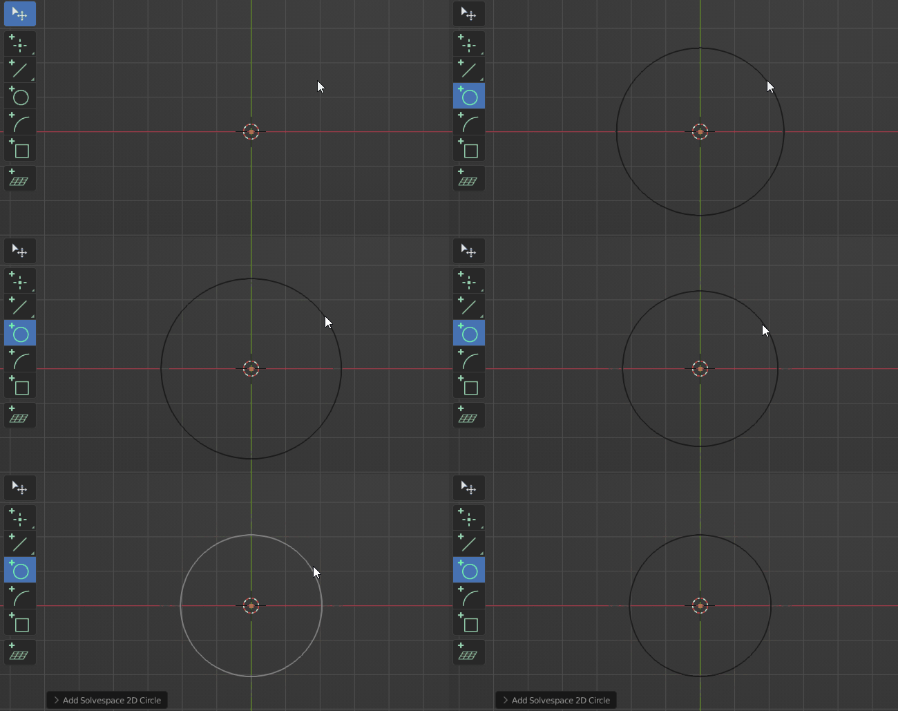
Let's take the "Circle" tool as an example. Since a circle is represented by its center and radius the tool will have two states. One to define the center element and one to set the radius.
State Types
A state can have two different kind of targets:
- Pointer
A pointer target is best described as a selection. Pointer states will prompt the user to select an element of the according type.
- Property
A property target simply represents a value of some kind like an integer or a float or a set of values to represent something like a location.
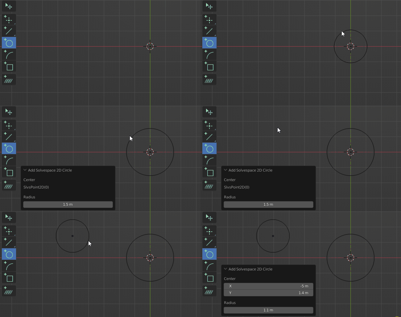 A state can however define both of those targets. In that case the property will be used to create a new element to satisfy the pointer target. This is often used to be able to place a new point at the mouse location when nothing is hovered but pick an existing point if one is hovered.
Selection vs Action
To be as flexible as possible the interaction system allows to work in different paradigms which can also be freely mixed. Those are:
-
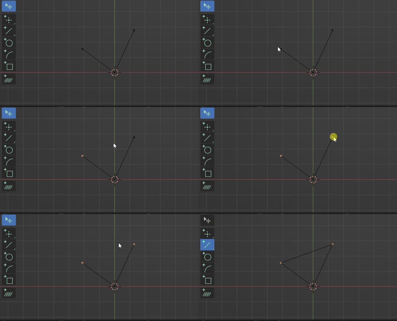
Select -> Invoke Operation (The standard way to work in blender)
-
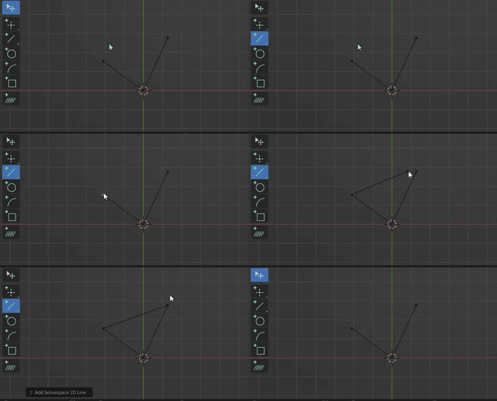
Invoke Operation -> Select
-
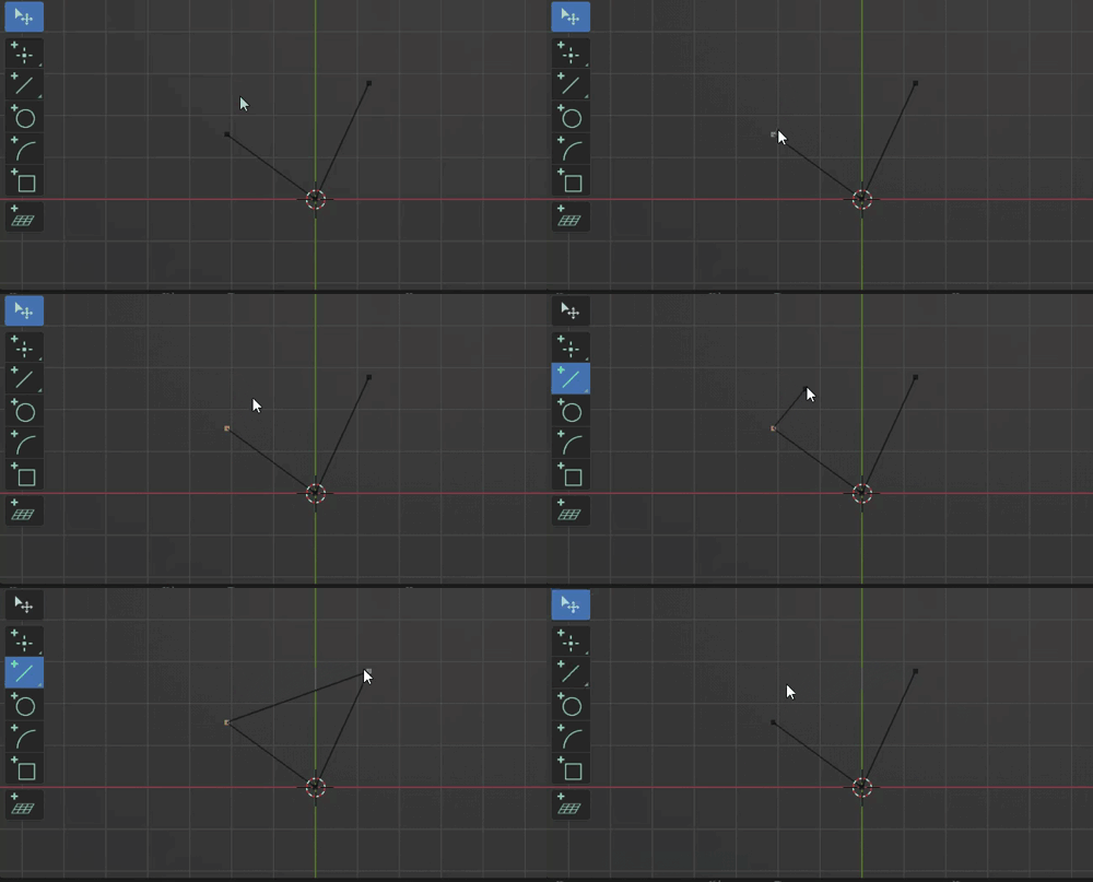
Partial Select -> Invoke Operation -> Select rest (Or set Parameters)
Numerical Edit
In order to precisely edit a states property, it's possible to edit values directly by entering numbers. When the stateproperty is a set of multiple values (e.g. XYZ Location) they will be treated as sub-states, meaning you can iterate (TAB) through them and enter values sequentially.
Description
When learning how a new tool works it's best to take a look at its tooltip, this will list the different states of the tool. For pointer states this will additionally display the accepted types that can be picked.
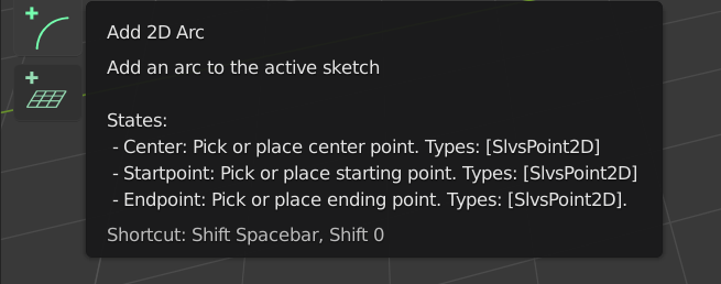
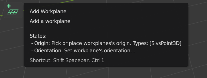
While running an operation the statusbar will display that information for the currently active state.

Continuous Drawing
The line and arc tools keep drawing: once a segment is placed the next one starts from its end point, sharing that point rather than putting a second one on top of it. The run ends when the segment's end lands on existing geometry (which is how a loop is closed), or with Esc.
Reaching for another of those tools mid-run carries on from where the chain got to: drawing lines and pressing the arc tool's shortcut starts the arc at the last line's end point, and the same the other way round. What the chain already drew stays; only the segment in progress is dropped.
Tools whose first click is not a start point (the center-based arc, circles) begin from scratch as usual, so reaching for one of those ends the run. Where several tools share a toolbar button and the shortcut stands for the whole group (the rectangle variants, the arrays), the key starts the member that can carry the chain on while one is waiting. The behaviour can be turned off per tool with the "Continuous Draw" checkbox in the tool header.
Immediate Execution
Most tools support immediate execution which will invoke the tools operations when switching to it and a valid selection is given.
Note that the execution is only triggered when a tool is invoked by its shortcut.
Snapping
When placing a sketch point you can snap it to existing 3D geometry in the scene. Snapping reuses Blender's native snap settings, so it's controlled from the snap dropdown in the 3D viewport header (Snap magnet toggle and the Snap To elements) rather than a separate setting.
Enable the Snap toggle and pick one or more snap elements; the extension reacts to:
- Vertex — mesh vertices and sketch points
- Edge — the closest point along a mesh edge or sketch segment
- Edge Center — the midpoint of an edge or segment
- Face Center — the center of a mesh face, or the centroid of a closed sketch shape (a circle or a shape drawn as a single closed curve)
Only the object directly under the cursor is considered, which keeps snapping responsive even in dense scenes. Snapping works both for other objects (meshes) and for other CAD Sketcher sketches.
Live Project Snaps
Snapping onto geometry outside the sketch normally keeps the reference: the element you snapped to is projected into the sketch, and the placed point is constrained to that projection, so editing or moving the source updates the sketch afterwards. This is the Live Project Snaps toggle in the tool settings bar of the drawing tools, on by default.
What the link looks like follows the snap element:
- Vertex — the vertex is projected as a point and the placed point coincides with it
- Edge — the edge is projected as a line and the point is kept on that line, free to slide along it
- Edge Center — the edge is projected and a midpoint constraint keeps the point centered
Other snap types, and geometry that can't be traced back to a source element, place a static point as before.
Turn the toggle off to get a plain static snap everywhere: the location is captured when the point is placed, with no projection and no constraint, so the point stays where it is when the source moves.
Hold Shift while placing or tweaking a point to temporarily bypass snapping.
Face-center snapping to a shape built from several separate lines (rather than one closed curve) is not supported — that region only exists in the generated mesh, which can't be inspected while sketching.
Auto Constraints
While drawing geometry the extension can infer and add obvious constraints for you automatically, so you don't have to place them by hand:
- Auto axis alignment — a segment drawn close to horizontal or vertical gets a Horizontal / Vertical constraint.
- Auto coincident — a new point placed on an existing point gets a Coincident constraint; placed on a line, arc or circle it gets a coincidence onto that curve, and on the midpoint of a snapped edge a Midpoint constraint.
- Auto joints — how a new segment meets the one it starts from or ends on: an arc carrying on smoothly from a line or another arc gets a Tangent constraint, and two lines meeting square or carrying straight on get Perpendicular / Parallel. Without these a chain of segments is connected but free to pivot, so it looks right only until something moves.
A constraint is only kept when it leaves the sketch solvable and actually takes a degree of freedom away, so nothing inferred can over-constrain a sketch: where the relation already follows from what is there (a square corner between a horizontal and a vertical line, say) no extra constraint is added.
This is controlled by the Auto Constraints toggle in the tool settings bar (top of the viewport) of the sketch tools — Line, Rectangle, Circle, Arc and Point. It's enabled by default.
Hold Shift while placing or confirming a point to skip the auto constraints for that step only, without having to change the toggle.